Warcraft MDL exporter for Blender By Kalle Halvarsson
Now also supports importing!
- Select your branch - 2.79 or 2.8 depending on your Blender version, and download/clone.
- Add export_mdl folder to a zip or rar file. It should be one next to the "images" folder - not the one containing the full repository!
- In Blender, go to User Preferences (CTRL+ALT+U) and select "Install Add-on From File". Select your zipped folder.
- MDL Exporter should now show up in the Import/Export plugins list. Make sure it is enabled by ticking the box.
- The option to export to .mdl will now appear in the export menu (you may need to restart Blender first).
This plugin tries to approximate the functionality of the Wc3 Art Tools exporter for 3ds Max. The ambition has been to support multiple ways of achieving the same result, so that users can set up their scene in whatever way feels most intuitive. There are, however, some implementation details you might need to know before using this plugin.
This exporter comes with a custom material editor which will attach extra MDL properties to the materials in your file. A material consists of multiple material layers, which will be rendered from top to bottom, and blended together using the specified filter mode. Some filter modes support an additional alpha multiplier, which can be animated. To add a texture animation, create a mapping node in the node graph with the same name as your layer, and animate its properties.

Previously, there was a fallback solution which would attempt to create a material based on your node setup. This has now been deprecated.
A "geoset" in an MDL file refers to a patch of geometry sharing the same material, vertex colors, and visibility (the latter two are stored in data blocks known as "geoset animations"). As such, assigning multiple materials onto the same object will cause it to be split into as many geosets. Geoset animations are generated by animating the render visibility of an object (see below) or by changing or animating its object color, which translates into vertex colors (vertex colors are treated as a global tint for the geoset). You can also add vertex colors to a material by adding an RGB input node anywhere in the node graph and naming it "VertexColor". This is convenient when have many small objects with the same material which should share tint.
Each geoset must be associated with at least one bone - if the mesh is not parented to a bone, one will be created for it. It is possible to skin an armature to a mesh - but make sure that each vertex is weighted to at least one bone, otherwise they will default to the armature root. The MDL format supports up to 3 bones influencing a single vertex - but these bones can't have individual weights, and will influence it equally. The exporter will discard extra bone weights with less than 25% influence, unless they are the only bone influencing a vertex.
An empty object whose name starts with "Bone_" can also be treated as a bone - this is sometimes useful for mechanical models. Bones with no geosets attached to them will be automatically converted into helpers.
A current issue is that auto-created root bones will not be combined even if they share the same geosets/geoset anims, to solve this it's good practice to always parent all your geosets to a manually created root bone. This will help reduce the amount of geosets and hence improve render performance (in GPU terms, each geoset generates a draw call).
It is possible to animate the position, scale and rotation of bones or meshes. You can also animate an object's visibility by keyframing the "render visibility" property (you can do this by holding your mouse over the render icon in the outliner and pressing the I key) - optionally, you can create a custom property called "visibility" and animate that. Using the Color field of an object, you can animate its tint value (setting the value to anything else but white will also create a static color GeosetAnim for it). Linear, DontInterp, and Bezier interpolation modes are currently supported, though rotations can only use Linear interpolation as of right now.
To mark sequences, create timeline markers (using the M key while hovering over the timeline) and rename them (using CTRL+M) to the name of your animation. Each sequence requires both a start and an end key with the same name. This approach was chosen over using acitons because it was deemed to be more intuitive and similar to how the process works in Wc3 Art Tools. If no sequence exists, a default one will be added on export.
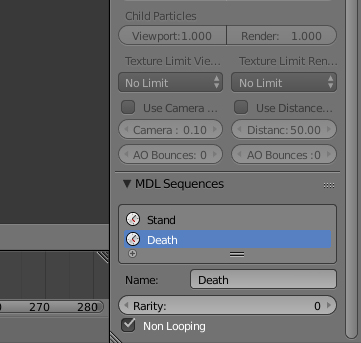
Whenever you create two timeline markers with the same name, a sequence will show up in the sequence manager tab, which is at the bottom of your scene tab in the properties menu. This is where you set things like looping and rarity - changing the name in the sequence editor will also change the corresponding timeline markers. If the name contains the word "Walk", you will also get to set a Movement Speed parameter which controls the relationship between the units movement speed and the walk animation playback rate. If you create a Death, Decay, or Attack animation, their non-looping values will default to "False" for convenience.
There is also a button below the sequence list where you can more conveniently create sequences. This operator will generate timeline markers at the specified keyframes, and you are also able to specify the looping and rarity properties.
Adding a "Cycles" modifier to an f-curve will create a global sequence around it. Global sequences always start from frame 0. It is enough that one of the f-curves in a group has a modifier for a global sequence to be created.
At the moment, IK controllers are only supported through resampling the entire animation into keyframes. This produces very dense data, so for these cases there is the option of applying a keyframe reduction algorithm to your animations based on a tolerance value. Three things to note about this feature:
- All animations optimized this way will have their interpolation forced to "Linear". This might be a desireable effect though, since it can further reduce file size.
- The tolerance threshold is the same for both rotations, translation and scale. For translation and scale, the value represents the maximum distance in meters that an optimized path can diverge before another keyframe is inserted. For rotation, this value is in the range of 0-2, where 0 means that the rotation is identical to the optimized frame, and 2 means they are anti-parallel. This distinction is important since some animation types can be more affected by the threshold than others.
- The optimizer works by recursively subdividing the sequence, adding new frames at whatever points produce the largest deviation from the original animation. However, it can only insert such keyframes in places where there was already a frame in the original animation, and as such it is not guaranteed to always produce the most optimal animation for any given motion, though it still produces good results.
The algorithm used is based on this paper: https://www.researchgate.net/publication/4343370_Keyframe_Reduction_Techniques_for_Motion_Capture_Data
Bones, lights and attachment points all support billboarding. A billboarding settings panel will automatically appear in the "object" properties tab when a relevant object is selected. You can constrain billboarding to a certain axis by checking the "Billboard Lock X/Y/Z" checkboxes respectively.
To create an attachment point, simply create an empty object and give it a name which ends with the word "Ref". For example, "Overhead Ref" will produce an attachment point called "Overhead". "Sprite First", "Sprite Second", etc. specify where flames will appear when a mechanical unit/structure is damaged.
Similar to attachments, event objects are created by giving an empty object a name which starts with an event type ("UBR" for UberSplat, "SND" for Sound, "FTP" for FootPrint, "SPL" for BloodSplat). The type is followed by a number ID (can be 'x'), and ends with the event identifier. An example of an event object is "SND1DHLB", which would produce a "Human Building Death (large)" sound. To animate the event, create a custom property called "eventtrack" and animate its value - the positions of the keyframes are used to trigger the event.
There is a helper operator for creating event objects which you can find by pressing the spacebar and searching for "Add MDL event track". These will give you fields where you can select the exact type and ID name from a list of names. There is also an option to search through the list.
Collision shapes in Warcraft are used primarily to define the selectable area of a unit, or the walkable area of a destructable. You can create theese by adding any geometric shape and naming it "CollisionBox" or "CollisionSphere". The exporter will use the bounds to calculate a radius or min/max points automatically. Note that collision boxes are always saved as axis aligned. There is a helper operator for quickly creating collision shapes named "Add MDL Collison Shape".
Cameras are exported as-is.
Create a light and go to the data tab where you will find a panel called "MDL Light Settings". "Attenuation Start" and "Attenuation End" control the falloff of the light's intensity. Most properties can be animated, including color.
The exporter has a custom editor for configuring particle systems. The data piggybacks on the Blender ParticleSystemSettings data block, so you need to create a particle system to make the MDL particle editor appear. This also allows for shared particle data among emitters - just remember to make it single-user first if you copy one so that you don't overwrite your old data. I've chosen to name the emitters "Model Emitter", and "Particle Emitter" rather than "ParticleEmitter" and "ParticleEmitter2", since it's more descriptive of what they do. Ribbons are also supported. The bounds of whatever object the particle system is attached to defines the width and height of the emitter - animating the X/Y scale of the object will animate the width and length of the exported emitter. Make sure not to apply the scale of the emitter since this will set the width/length to be 1 regardless of the actual emitter size (fix for this is in the works).

- When using empties as bones: all translation animations will be transformed to be relative to the object on the first frame, since Blender stores animations in absolute world position while MDL models store translation as relative to the rest pose and parent. This might cause some issues in situations where the bone is a child of a bone with a rotation animation, though i'm not sure.
- Support for animated witdh/length for particle systems is currently broken.
This plugin is now also capable of importing MDL files. A major benefit of this is that it effectively works as reference for how to replicate the behaviour of native models when making your own.
The importer will auto-generate node setups for all materials. If a material layer uses an image, the importer will attempt to load a .PNG file with the same name in the same folder as the source model - so if you have extracted all textures before importing, the model will look as in-game out of the box. Team color is represented by a solid red RGB node, team glow by a red-tinted spherical gradient, and replaceable textures by a checker texture. Vertex coloring will be multiplied in. Overall, the system will create mix nodes to combine layers in quite a sophisticated way, and set the correct alpha output (though keep in mind that if the image is missing, the alpha will be null, making the material appear transparent in previews)

Geosets with more than one matrix group will be imported as a skinned mesh, and all bones that are parents of a skinned bone will be added to an armature. There will only ever be one armature created. Bones will be oriented towards their child, unless there is more than one child, in which case it will orient towards their average position. It's very hard to replicate the original bone structure, but this provides good results in most cases.
- Ribbon and model emitters are not supported yet.
- Some value animations might not be imported correctly
- Cameras and lights are still fairly untested
- Hermite interpolation for rotation animations is currently not supported - will default to linear.